Position of the load cell to measure the press-fit load correctly
In this article, I will be talking about the theme of "Position of the load cell to measure the press-fit load correctly".
The press-fit process, which is commonly used in general assembly processes, is described here, with a focus on overviews, methods for correctly detecting press-fit loads, and failure cases.
- Basic Structure of Press Machine -
First of all, the basic mechanism of the press is as follows.
- Purpose: Used in press fitting and caulking processes
- Press mechanism: Hydraulic drive, servo drive, etc.
- Judgment items (in case of press fitting): Press fitting load and press fitting dimensions
The technique itself has not changed for a long time, although the number of servo-driven ones is increasing these days. It is a simple operation to assemble the parts by applying load at low speed. The theme of this article is focused on "Press-Fit Load".
What is press-fit load?
I don't think it's necessary to explain it, but in simple terms, it's a method of assembling two parts ( shaft and hole) by applying strong load to them. The load at that time is called the "press fit load". With time on the horizontal axis and load on the vertical axis, the press-in waveform is as follows.
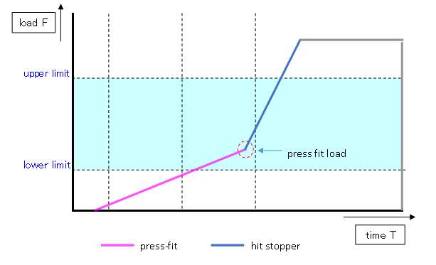
- Press-fitting of two parts has begun in the pink area.
- The dark blue part is the state in which press-fitting has been completed and has hit the stopper.
*To guarantee the press fit dimensions, the press fit process is stopped by pressing against the stopper.
This blue starting load (the load that hit the stopper after the press-fit operation was completed) is the "press-fit load".
Case Study of bad press machine
When I was in my fourth or fifth year with the company, I made one mistake with this press-fit load. The press-fit load was smaller than specified, and I was very suspicious of the parts and load design. The problem, however, was on the equipment side.
Equipment structure and problems at that time
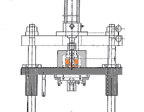
The orange part is load cell.
As shown in the above figure, the slider and the jig for the press part are located under the load cell, and the weight of the set of jigs hanging under the load cell is about 50kg.
However, since the load cell cannot feel the weight of the jig, the load displayed on the load cell will be 50 kg less than the actual press load.
If the estimated press-in load is 1000 kg, this is not much of a problem, but if the expected press-in load is 100 kg, this 50 kg difference is a major problem.
Recommended equipment structure
Then, the position of the load cell that should be placed is as follows
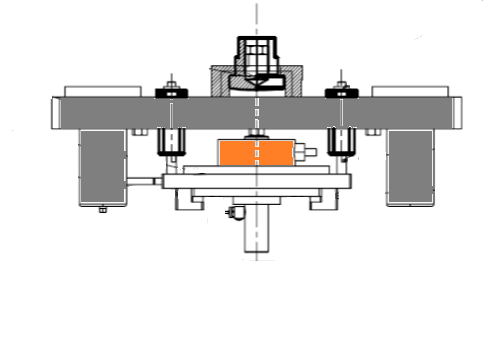
As you can see from the figure, the difference is the location of the load cell.
In order to measure the load correctly, load cell should be placed underneath the slider.
If you have an understanding of mechanics at the high school physics level, you should be able to understand the difference.
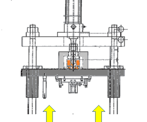
At the time, we found this problem after mass production had begun, so we couldn't modify the load cell position.
Instead, the slider can be guided by load equivalent to 50kg from the bottom to cancel the weight of the jig (see below).
This way, an extra 50 kg of press load from above is required and the function is the same.
Note: Relationship between interference and press fit load
The press-fit load is determined by the interference between two parts. In most cases, the press-fit load problem is either component problem (poor dimensions) or load setting problem (specification mistake). There is little that can be adjusted on the press side. The only way to make sure the equipment is OK is to confirm following
- load cell correctly calibrated
- inflection point correctly detected
- press-in speed not too fast
- centering between upper and lower unir
Assuming that the equipment and components are in the correct condition, here is one way to verify that there are no problems with the specification settings of the press-in load.
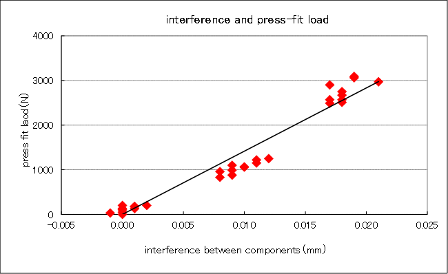
The press-fit load depends on the part's interference (how tightly fitted it is).
Simply put, the tighter the interference, the higher the press-fit load.
The looser the interference, the lower the press-fit load.
The following graph shows this relationship.
Using the worst of the part's tolerance (maximum tolerance, minimum tolerance), you can draw this graph to see if the set load is correct.
summary
In this article, I have explained the relationship between the location of the load cell and the press-fit load.
It's a strange thing. There were a lot of engineers around at the time, including people from the equipment manufacturing company, and they were all looking at these kinds of failures. No one noticed.
It's a blind spot until you dig deeper into the problem. There were a lot of people who came from college engineering, not just high school physics, but this is exactly what happened.
There are many things that you do without thinking much, but that you find strange after you dig deeper into the problem.
We should be careful not to get caught up in the daily routine of work and stop thinking.
RELATED BOOK) production engineering guide
RELATED) Problem Analysis Methods (Histogram)
RELATED) Introduction of caulking process
RELATED) Introduction and Use of FTA